TankFC – Prototyping walk through

Detailed steps of my DIY flight controller prototype assembly and testing journey

Table of Contents

PCB sourcing

Quality PCB prototyping had become very affordable to maker during the last decade, as there is a lot of cheap PCB house that allow you to get a 2 layer PCB for less then 10€ shipped. They manage to get those prices by regrouping a bunch of design into single manufacturing batch. So to get those low price, your PCB must stay within the most common specification (1.6mm thickness, etc..).

The PCB of the TANKFC is more expensive, as it has some more advanced specifications:

  • 1mm thickness
  • 4 layers
  • Gold surface finish
  • PCB edge plating for the cooling tabs
PCB edge plating example

The edge plating specification was the most difficult to get for a cheap price, as it is quite uncommon and need some additionnal manufacturing steps. I ordered the PCB from JLCPCB, as their website claimed they were doing edge plating. They also offer a very affordable sourcing and assembly service (more about it in the sections below).

Global PCB quality is good, but there was a bit of misunderstanding about the PCB edge plating, which wasn’t present..Not a big deal, but it definitly doesn’t look as nice.

Components sourcing

As a maker, it may be difficult to get some components at a decent price. Online shop like Mouser or Farnell are the easiest and quickest way to order your BOM, but are very expensive. An other solution, which require patience, is to order each component from Aliexpress or similar. But to assemble my flight controller prototype, I mainly scavanged components from others boards. The main donator was a Noxe F4, which can be purchased for 10€, far less than it’s BOM value at retail price here in Europe. I also used components from old dead flight controller and completed the BOM with a Mouser order. 

Board assembly

Most of the bottom layer was assembled directly by JLPCB, including the STM32F722 and flash IC. This saved me a lot of work, as there were a lot of small passive components on this layer. I assembled the top layer using a stencil/solder paste/reflow technic, similar to the method I used on my Power bank build.

During assembly, I discovered that the footprint of the barometer chip was mirrored. Turn out I just followed a bottom view of the component when drawing the footprint.. And because it is so small, I didn’t even tried to find a workaround to make it work. Hopefully, it is not a crucial sensor for the flight controller.

Testing

Functional tests

So how do we test a brand new flight controller ? Well, most of the functions can be checked through Betaflight GUI. So I started by installing Betaflight with the custom target previously created. A fresh STM32 micro-controlleur never programmed will start in DFU mode by default. So in theory, I just had to plug it to my computer and flash it like any other flight controller. But of course things didn’t went so easily. When plugged in, nothing was detected by my computer. Time for some troubleshooting.

Power supply check

The first thing to check when troubleshooting a new design are the different power supply. On this board, there is the 5V rail, and two 3V3 rails. The 5V rail was working properly, both when powered from battery or by USB. But none of the 3V3 rails were working. A quick check on the component layout showed that the footprint was mirrored.. Fortunatly, I managed to solder them upside down without much trouble. It’s even quite clean for a PCB fix, you wouldn’t notice it if not searching for it.

After fixing both LDO, the STM32F7 IC was working much better, and I then flashed Betaflight without any issues.

Onboard Peripheral testing

Straight from the Betaflighh configurator, both accelerometer and blackbox flash storage were detected. Very good, not much more to do here, maiden flight will be the real test for the gyroscope.

On the other hand, I spent some time debugging the OSD chip. I wasn’t getting any video at all on it’s output, like if the IC was damaged. After some headache, I finally found the issue : the 27Mhz quartz wasn’t working. Guess what ? An other mirrored footprint ! This time the fix isn’t very elegant, but the OSD is a must have on a flight controller. I glued the quartz upside down on the PCB near the original footprint, and added some straps.

External peripheral testing

Next to be tested were the external components: Vtx, Rx, and GPS module.After some hardware and software tweaking, everything is working fine. It’s very satisfying to get each function working one after an other. The FC also get it’s final look with the soldering of the Vtx and Rx. modules.

Video power circuit

Most of the error encoutered so far are implementation error (small mistake on schematic or in the routing), which will be easily fix in the next batch. But during the testing of the video circuit, I came accros an architecture problem.

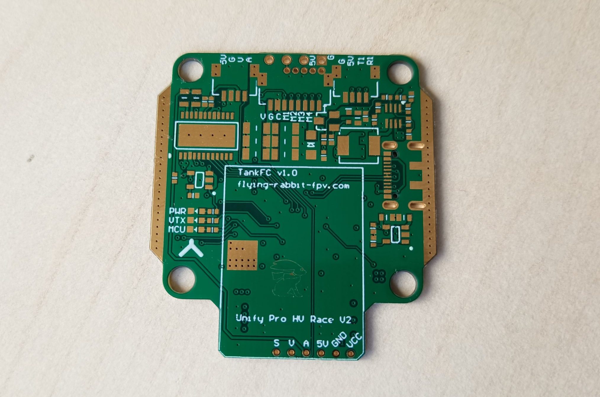
Remember the solder bridge to select the power source for the video part of the board ? It’s purpose was to power the OSD chip and the camera from either the Vtx 5V or the board 5V. But when configured for Vtx 5V, the OSD wasn’t working.

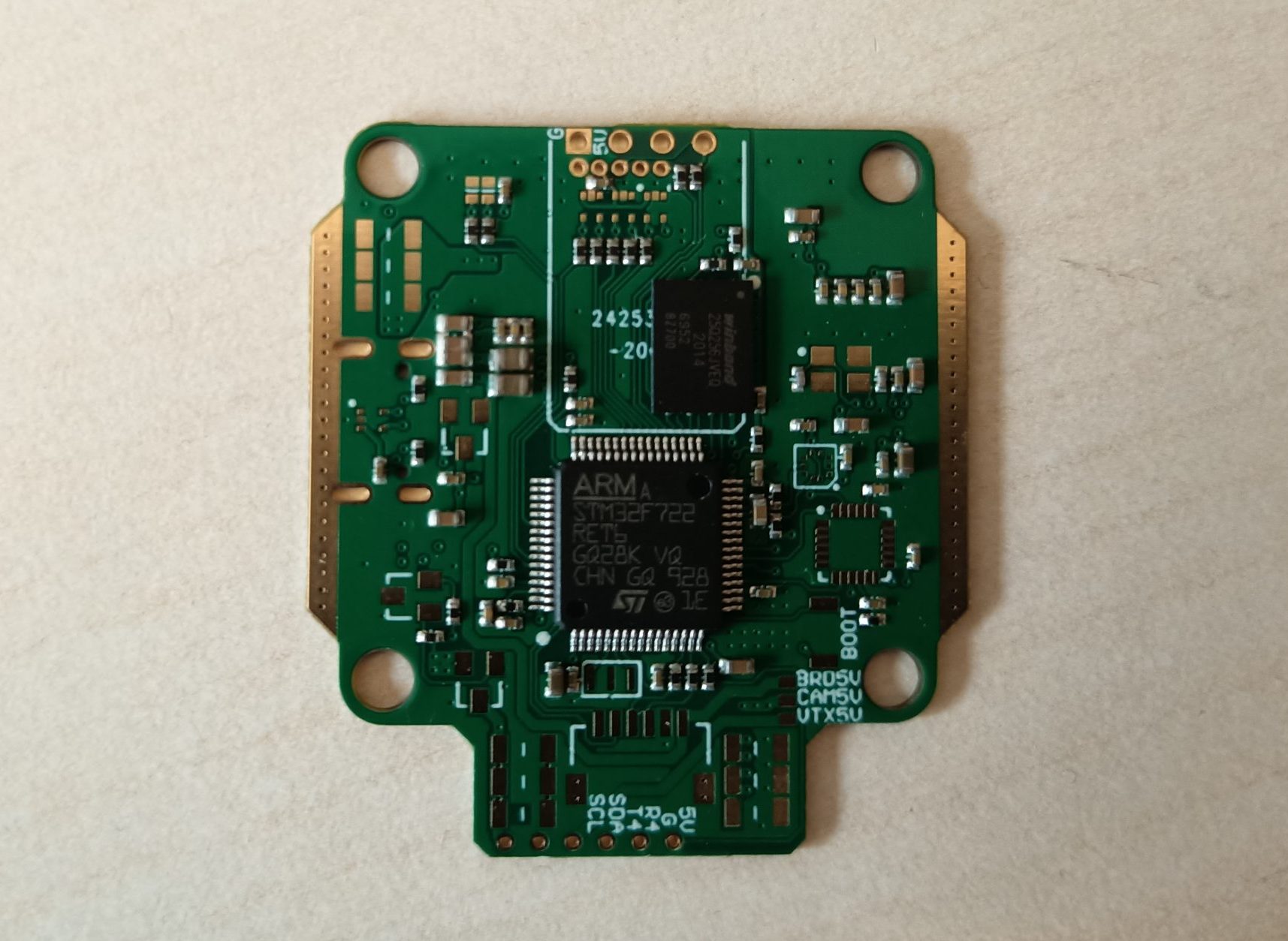
I’m pretty sure it’s a power sequencing issue. After some analysis, I’ve found out that the Vtx takes few second to output 5V. By this time, the STM32 MCU has booted, and didn’t detect any OSD chip (because it is not powered yet). Therefore, it disables the OSD function. So when 5V is finally applied to the video circuit, the OSD chip don’t receive any  commands from the MCU.


There is a lot of possibility to address this behavior, either software or hardware. I won’t look into software solution, as I want to keep my board compatible with the standard betaflight code. On the hardware side, I see two approaches :

    • Making sure the OSD chip is powered simultaneously as the STM32
    • Making sure the STM32 doesn’t boot until the OSD chip is powered

A big constraint for this problem is the fact that the Vtx is not powered until the STM32 has booted du to the real PIT function which is OFF by default. Let’s fly with the onboard 5V for now and continue the testing, I will dive into it when designing the next board revision.

Flight test

To quickly get this board in the air, I dismantled my FlossTank build and reuse the ESC. Probably the easiest and quickest build I’ve ever done ! Not the cleanest, but it’s just a temporary test bench.

Maiden flight went very smoothly, the quad didn’t experienced any noise related behavior. Video signal signal was crystal clear, the large amount of filtering paired with the TBS Vtx is a really nice combo. I’m proud to declare this flight controller airworthy !

Conclusion

As my first home-made flight controller, I’m very pleased with the board I ended up with. I will now fly it for a while to challenge it’s durability and reliability. A new version of the board will follow to fix the existing issues, but also to add some new feature ideas !

Leave a Reply

Your email address will not be published. Required fields are marked *